
Professional Diploma in Electronic Circuit Diagnosis and Repair
This professional diploma prepares you to find and fix faults in electronic circuit boards with method and precision. You will study circuit analysis and components, advanced instrumentation such as oscilloscopes, logic analysers and thermal cameras, systematic fault-finding methods, linear and switch-mode power supplies, analog and power electronics, digital circuits and microcontrollers, through-hole and SMD soldering and rework, and how to run a repair workshop with proper documentation and quality control.
Prior knowledge check
These are the skills this program gives you. Tick the ones you already master and we will tell you which part of the syllabus is for you.
You are starting from scratch in this subject. The program is designed precisely for that.
What is the Professional Diploma in Electronic Circuit Diagnosis and Repair?
This professional diploma prepares you to diagnose and repair electronic boards at component level, the skill that keeps onboard, industrial and consumer equipment running instead of being replaced. You will learn to apply Ohm's and Kirchhoff's laws to diagnosis, read schematics and datasheets, use multimeters, oscilloscopes, signal generators, ESR meters, curve tracers and thermal cameras, isolate faults with top-down, bottom-up and block-division strategies, repair linear and switch-mode power supplies, amplifiers, motor drivers and microcontroller systems, recover firmware, and rework THT, SMD, QFP and BGA components and damaged PCB tracks.
What sets this professional diploma apart: a systematic fault-finding methodology based on decision trees and diagnostic flowcharts; advanced instrumentation, from in-circuit measurements to thermal imaging and voltage injection; in-depth coverage of switch-mode power supplies, one of the most common sources of failure; a balanced view of analog, power and digital electronics, including communication buses such as I2C, SPI, UART and CAN; professional soldering and rework techniques, from SMD to an introduction to BGA reballing; and a final project in which you solve and document a complex board-level fault.
Program highlights
- Systematic fault-finding: decision trees, flowcharts and block isolation.
- Advanced instrumentation: oscilloscope, logic analyzer, ESR meter and thermal camera.
- Switch-mode power supplies: primary, secondary, PWM control and MOSFET/IGBT faults.
- Digital electronics: I2C, SPI, UART and CAN buses, memories and firmware recovery.
- Professional rework: THT, SMD, QFP, BGA and PCB track repair.
- Final project: solving and reporting on a complex board-level fault.
Syllabus of the Professional Diploma in Electronic Circuit Diagnosis and Repair
8 modules. Select a module to see its content.
Fundamentals of circuit and component analysis
- 1.1. Fundamental electrical laws applied to diagnosis (Ohm, Kirchhoff)
- 1.2. DC and AC circuit analysis
- 1.3. Identification and behavior of passive components (resistors, capacitors, inductors)
- 1.4. Operation and common faults of semiconductor components (diodes, BJT and FET transistors)
- 1.5. Optoelectronic and protection components (fuses, varistors, optocouplers)
- 1.6. Reading and interpreting schematics, block diagrams and datasheets
- 1.7. Basic workshop tools: soldering station, multimeter and variable power supplies
- 1.8. Reading electronic schematics
Advanced instrumentation and measurement techniques
- 2.1. Advanced use of the digital multimeter: precision and in-circuit measurements
- 2.2. Using the oscilloscope: frequency, waveform and transient capture
- 2.3. Using signal generators and logic analysers in diagnosis
- 2.4. ESR meters for capacitors and in-circuit component testers
- 2.5. Thermal cameras and infrared inspection to locate short circuits
- 2.6. Curve tracers and signal injection for fault tracing
- 2.7. Calibration, safe equipment handling and ESD protection
- 2.8. Oscilloscopes and analysers
Systematic fault diagnosis methodology
- 3.1. Fault isolation strategies: top-down, bottom-up and block division
- 3.2. Diagnosis by visual and smell inspection: signs of overheating and mechanical damage
- 3.3. Symptom analysis and interpretation of error codes and abnormal behavior
- 3.4. Cold impedance measurement (unpowered) and continuity tests
- 3.5. Dynamic tests under power and current consumption analysis
- 3.6. Voltage injection technique to find shorted components
- 3.7. Building decision trees and diagnostic flowcharts
- 3.8. Fault trees and diagnosis
Power supply diagnosis and repair
- 4.1. Architecture and typical faults of linear power supplies
- 4.2. Operating principle and topologies of switch-mode power supplies (SMPS)
- 4.3. Identifying and isolating faults in the primary (high-voltage) stage
- 4.4. Diagnosing the secondary stage, feedback circuits and optocouplers
- 4.5. Faults in PWM control ICs and switching transistors (MOSFET/IGBT)
- 4.6. Safe procedures for repairing and replacing parts in switch-mode supplies
- 4.7. Load tests, voltage regulation and ripple filtering
- 4.8. Switch-mode power supplies
Analog electronics and power circuits
- 5.1. Diagnosing operational amplifiers and signal conditioning circuits
- 5.2. Locating faults in power stages and audio/RF amplification
- 5.3. Repairing circuits with thyristors, SCRs and triacs in power control
- 5.4. Fault analysis in H-bridges and motor drivers
- 5.5. Detecting electrical noise, distortion and unwanted oscillations
- 5.6. Adjustment, bias calibration and balancing in analog stages
- 5.7. Replacing discontinued components and selecting direct equivalents
- 5.8. Amplifiers and regulators
Digital circuits and microcontrollers
- 6.1. Diagnosing digital logic: logic gates, multiplexers and flip-flops
- 6.2. Analyzing serial and parallel communication buses (I2C, SPI, UART, CAN)
- 6.3. Checking clock lines, crystal oscillators and reset signals
- 6.4. Identifying faults in memories (EEPROM, Flash, RAM)
- 6.5. Diagnosing microcontroller and microprocessor-based systems
- 6.6. Firmware extraction and read/write techniques for board recovery
- 6.7. Isolating software problems from hardware faults
- 6.8. Microcontroller programming
Advanced desoldering, soldering and rework techniques
- 7.1. Soldering and desoldering procedures for through-hole (THT) components
- 7.2. Rework techniques for surface-mount (SMD) components
- 7.3. Using hot-air stations and board preheaters
- 7.4. Replacing QFP, SOIC and SOT ICs and multi-pin connectors
- 7.5. Introduction to reballing and replacing BGA ICs
- 7.6. Repairing cut tracks and lifted pads and rebuilding PCBs
- 7.7. Cleaning, UV solder mask application and professional board finishing
- 7.8. SMD soldering
Workshop management, documentation and practical cases
- 8.1. Documenting the repair process and recording fault histories
- 8.2. Managing spare parts stock, critical components and suppliers
- 8.3. Economic feasibility analysis: repair versus replacing the whole board
- 8.4. Burn-in testing and post-repair quality control
- 8.5. Biological and electrical safety rules and electronic waste (WEEE) handling
- 8.6. Real case studies: diagnosis and repair in industrial and consumer electronics
- 8.7. Repair records
- 8.8. Final project: solving a complex board-level fault and writing the technical report
Duration and format of the Professional Diploma in Electronic Circuit Diagnosis and Repair
It is 800 hours. Tell us how many you can study each week and we will tell you when you will really finish.
This is the pace at which most students finish. It fits well with the installment plan.
Academic leadership and faculty
The Navalis teaching team: working professionals who teach and supervise the programs.
 Dr. Marina AlcoverAcademic Director and Head of Quality Assurance
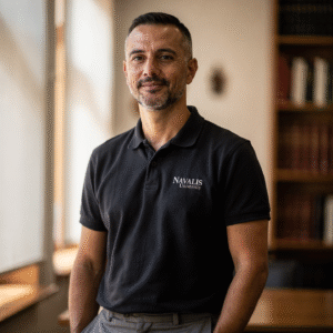 Eng. Diego CifuentesSenior Lecturer in Naval Welding and Non-Destructive Testing; Head of QA/QC for Welded Joints
 Capt. Javier Abaroa (MCA)Senior Lecturer in Ship Handling, Electronic Navigation (ECDIS/Radar/ARPA) and GMDSS; STCW Compliance and Bridge Resource Management Coordinator
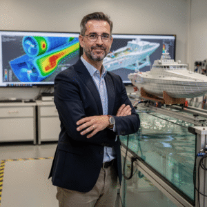 Dr. Pau FerrerSenior Lecturer in Naval Architecture and Simulation; Director of the Hydrodynamics and CFD Laboratory
 Dr. Nuria LlobregatSenior Lecturer in Marine Meteorology, SAR and Operational Safety; Navigation Risk Management Coordinator
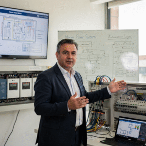 Eng. Javier BañulsSenior Lecturer in Electrical Engineering, Automation and ETO Engineering; Electronic Integration and Engine Alarms Coordinator
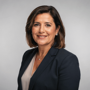 Eng. Sofía MarquinaSenior Lecturer in Materials, Composites and Corrosion Protection; Coordinator of the Advanced Paints and Coatings Line
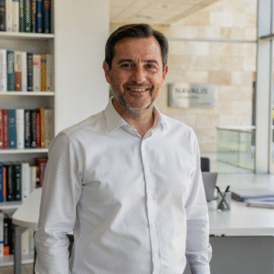 Eng. Tomás RieraSenior Lecturer in Propulsion, Alternative Energy and Hybrid Systems; Energy Performance and Vibration Coordinator
Objectives of the Professional Diploma in Electronic Circuit Diagnosis and Repair
Career opportunities after the Professional Diploma in Electronic Circuit Diagnosis and Repair
Questions about the Professional Diploma in Electronic Circuit Diagnosis and Repair
You will be able to diagnose and repair electronic circuits at component level using a systematic method and professional instruments.
Yes. Basic knowledge of components, simple circuits, measuring instruments and soldering is recommended.
Yes. The methods apply to the electronic boards found in onboard equipment as well as in industrial and consumer electronics.
Digital multimeter, oscilloscope, signal generator, logic analyzer, ESR meter, curve tracer and thermal camera, among others.
It is not required to follow the program, but having a multimeter and a soldering station will help you practice what you learn.
You solve a complex board-level fault and write a technical report documenting the diagnosis, repair and verification.
Fully online, through a virtual campus available 24/7, with live sessions that are recorded and tutorials with the teaching staff.
The professional diploma comprises 800 hours of study across 8 modules of about 100 hours each and ends with a final project. You can progress at your own pace within the schedule set when you enroll.
More programs in Machinery and electrics
Admission process
No waiting for a call back. If your documents are in order, you can enroll in the same session.
- Profile: aimed at electronics technicians and electricians, electronic and mechatronic engineers, engineering and technical students, maintenance managers and workshop supervisors, and owners of electronic repair businesses. A higher technical qualification in electronics, electricity, mechatronics or a similar field, or demonstrable professional experience in electronic repair, is recommended, together with basic knowledge of electronics, measuring instruments and soldering.
- Language: sufficient command of English to follow the classes and the technical documentation.
- Technical resources: a computer with a stable internet connection, an up-to-date browser and a camera for live sessions and project presentations; schematic viewing software is useful.
- Admission: online application, review of your profile and a short interview with the academic team.
- 01ApplicationYour details, background and documents.
- 02Instant reviewWe check that everything is complete and in order.
- 03EnrollmentChoose full payment or instalments and reserve your place.
Admission is provisional until the committee validates the documents provided. If you do not meet the requirements, the full amount is refunded.
Ask us before you enroll
Leave your details and admissions will write to you to answer any questions. If you are already sure, you can apply and pay in the same session.